The HB100 microwave module has been around for a number of years. This inexpensive 10 GHz device is more often used as a motion detector, but is easily re-purposed as a transmitter, receiver, or both at the same time for all different types of signals, wide or narrow.
Amateur radio operators have a luxury that other hobbies that involve some form of wireless communications do not have. With over 23,000 MHz of spectrum available via the easiest to obtain "Technician Class" license in the United States, there is a much wider world to explore.
Moving forward with amateur 3 cm band communication
Between 10,000 MHz and 10,500 is the 3 cm US technician amateur radio license band that falls into the SHF spectrum segment.
There are some interesting neighbors adjacent to the amateur spectrum according to the Federal Communications Commission (FCC) spectrum chart excerpt below just to see how in demand and valuable this spectrum is.
There are some interesting neighbors adjacent to the amateur spectrum according to the Federal Communications Commission (FCC) spectrum chart excerpt below just to see how in demand and valuable this spectrum is.
Here is a list of things you will need to get started to receive signals on 10 GHz:
- USB SDR dongle (RTL-SDR V3 recommended)
- Appropriate cabling to hook this all together
Above links are just suggestions. The most critical things when shopping for above include:
Power Supply: The power supply must be capable of an output of 13 and/or 18 volts. The LNB changes antenna polarization based on the voltage powering it, so a supply capable of this range is required. A fixed voltage power supply would be best however in order to not damage your LNB. Many laptop computer power supplies can easily re-purposed for this with appropriate additional circuitry. Just be careful when making adjustments with a variable supply as going over 18 volts may damage your LNB.
Bias T: The RF DC Bias T allows DC power to be sent one way to power the LNB while blocking the DC power from being back fed into your USB SDR receiver. Being sure to follow proper connection direction is critical to not damage any of your 10 GHz equipment and also, your computer which will NOT like 18 volts being sent into the SDR and possibly into your laptop USB port. It is worth noting that the RTL-SDR v3 does have a built in DC bias T, but is not capable of outputs anywhere close to what the LNB needs.
LNB: The LNB is what converts the 10 GHz signal down to a lower intermediate frequency that can be received by your SDR between the 600 to 900 MHz range. It is far easier to send this signal over common 75 ohm coaxial cable over 100 feet into your Bias T and then into your SDR than trying to transport a 10 GHz signal cheaply.
Beyond above three items, the appropriate cabling for power and feed lines are needed. Do not use multiple RF adapters to change from connections like SMA to BNC to BNC to F as you will lose precious signal as a cautionary note.
Optional, but mandatory once you get things working for short range is to use this receiver with a dish antenna, such as the easily found "Direct TV" or "Dish Network" artifacts via Craigslist, Facebook Market Place and many other local sources. The dish will help concentrate signals for longer range reception or communication.
Your finished 10 GHz receiver should look like this:
Software for receiving 10 GHz signals
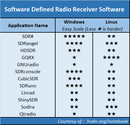
Here are where things become a matter of preference as there are many different software packages that will work for 10 GHz. One of the easiest programs to get working is called SDR# where a more advanced and capable application is SDRangel, which also includes native video reception.
A list of software to be mindful of includes:
What about that HB100?
Sometimes it is easier to start with the harder part and that was the receiver component for those interested in 10 GHz signals. The good news on the transmitter part is that it is easy and cheap to make a basic transmitter capable of voice or video transmission.
Inside the HB100, is a rather simple circuit but very complex design.
All of the traces on the PCB and placement of the few components all play a part in how the HB100 actually functions. Here is a schematic description courtesy of All About Circuits.
By simply adding a signal that can ride on top of the power supply source, you can easily modulate the HB100 with either voice or video signals.
A simple circuit that provides regulated power, audio pre-amplifier and modulation for the HB100 is referenced below from the presentation "Build a simple 3cm transmitter" created by Cor Rademeyer, ZS6CR in 2018.
------
Some recent popular SDR related HVDN Notebook pages


This comment has been removed by the author.
ReplyDeleteIs there link to second part of the article?
ReplyDeleteWWW.CE3VNA.CL
DeleteHi, A very interesting article but I cant seem to find the link anywhere on the page to the second part of the article relating to video modulation of the HB100?
ReplyDelete